|
Our 1985 Eagle 10 Bus Conversion Project Page 2
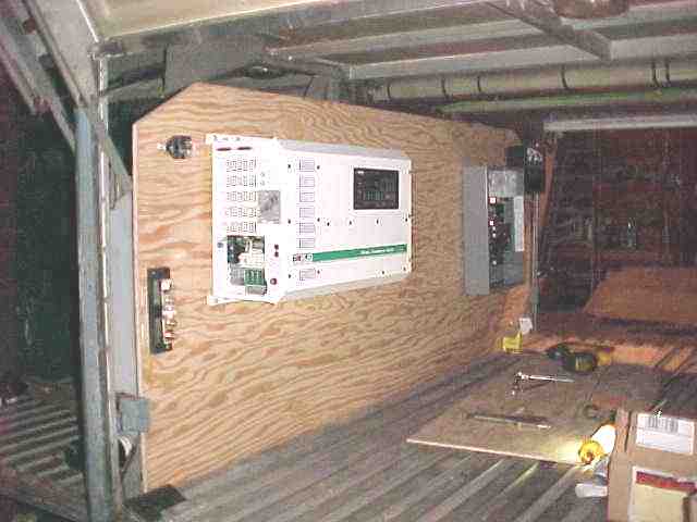
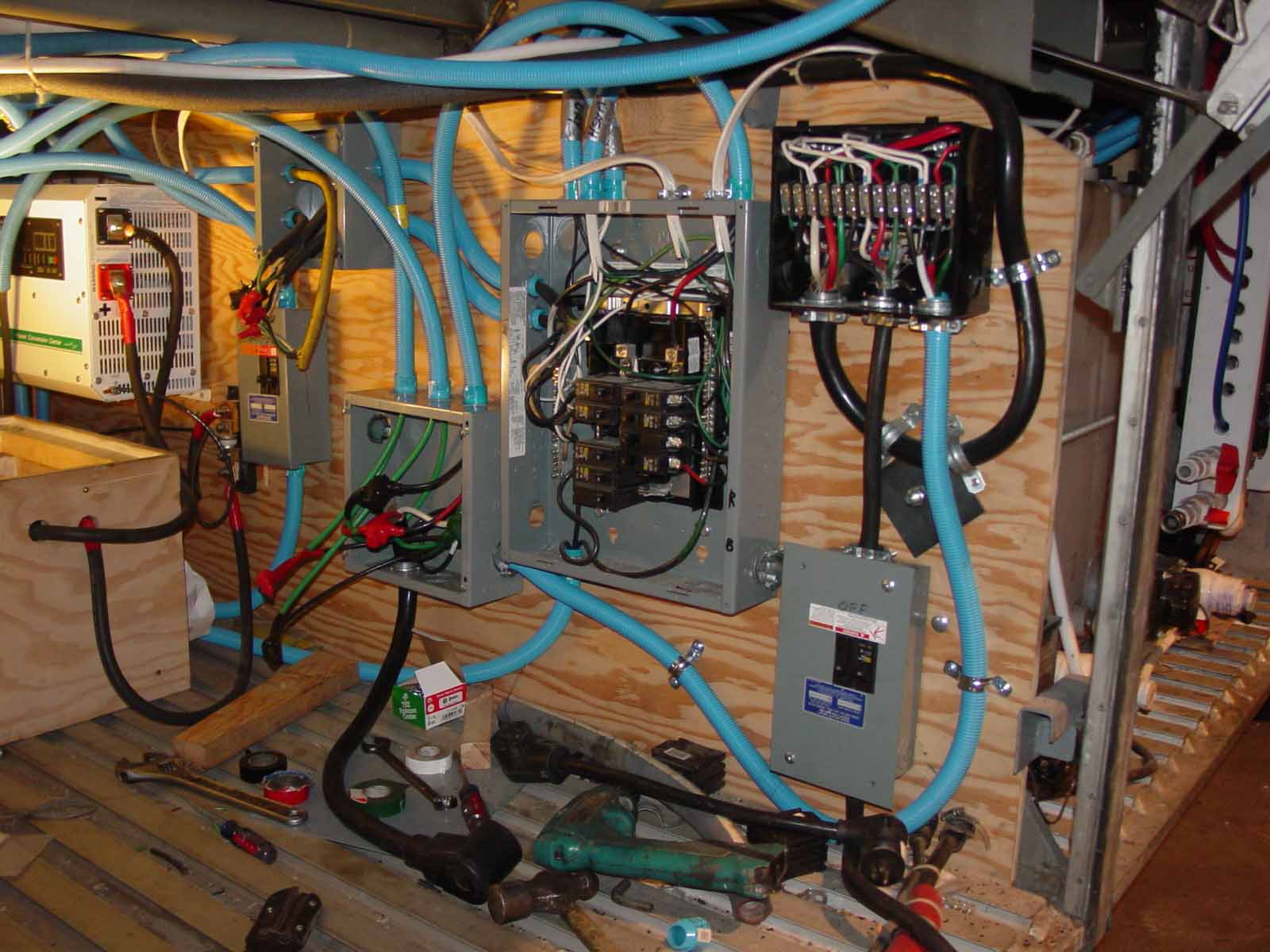
In each of the three bays under the passenger area, I installed plywood bulkheads. In order to do this, I welded tabs to the existing frames and then bolted the plywood to the tabs. In the left picture you can see the Trace 2512 full wave inverter mounted along with the 400 amp breaker for the battery feed to the inverter. This inverter furnishes 120 volt power to the motorhome from a bank of batteries. When the bus has 120 volt power available (either shore power or generator), it then becomes a very powerful and sophisticated battery charger for the supply batteries. In the picture on the left, the main breaker box is installed as well as the transfer switch. The transfer switch controls the switching from shore power to generator so that the switch is made cleanly with no chance of mixing the two sources.
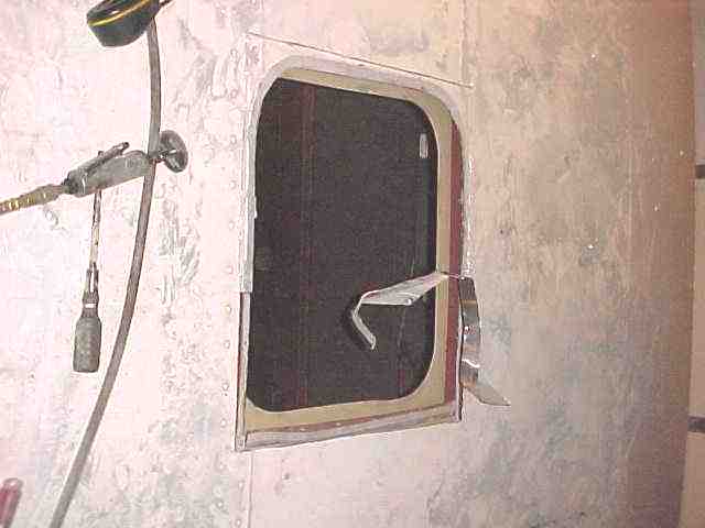
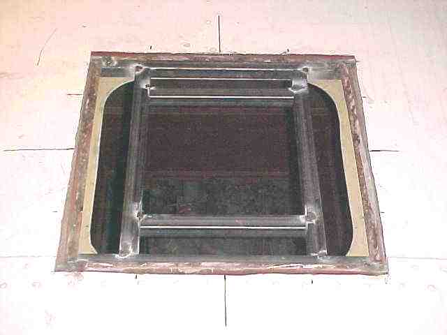
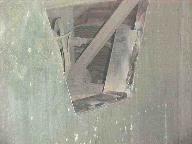
August 2002. I started working on the generator and radiator boxes. Shown in the photos above are a couple of photos of the front bay and the opening that was cut for the intake to the radiator box. The shape of the opening was dictated by the front bay frame geometry. Because the opening is exposed to wheel debris, I welded in deflectors to keep most of the material out of the radiator box.
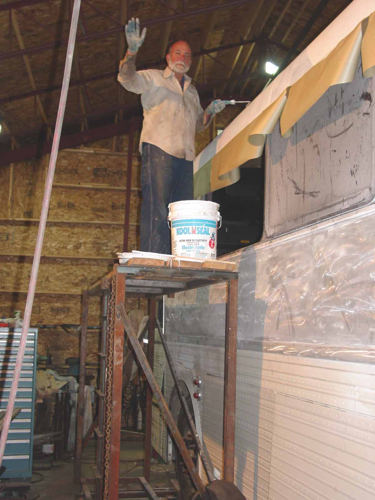
December 2002. In late December I spent quite a bit of time working on the single piece front door and filling/sealing the roof for the air conditioners. I used Kool Seal material to seal roof. I also removed the right side destination marker and filled it in with sheet aluminum. Also I continued work on Generator box. Shown in the photo is a scaffold that I built. It was first mounted on the top of my Jeep Scrambler to help me build my shop (21 feet at the peak). I then converted it to use while working on the side and roof of the bus.
2003. Up to this point in the documentation, I have been logging the work as I got a chance. Well, a whole year has gone by and I have not done any updating. So, we will just jump into a discussion of some of the major projects that have been accomplished in 2003.
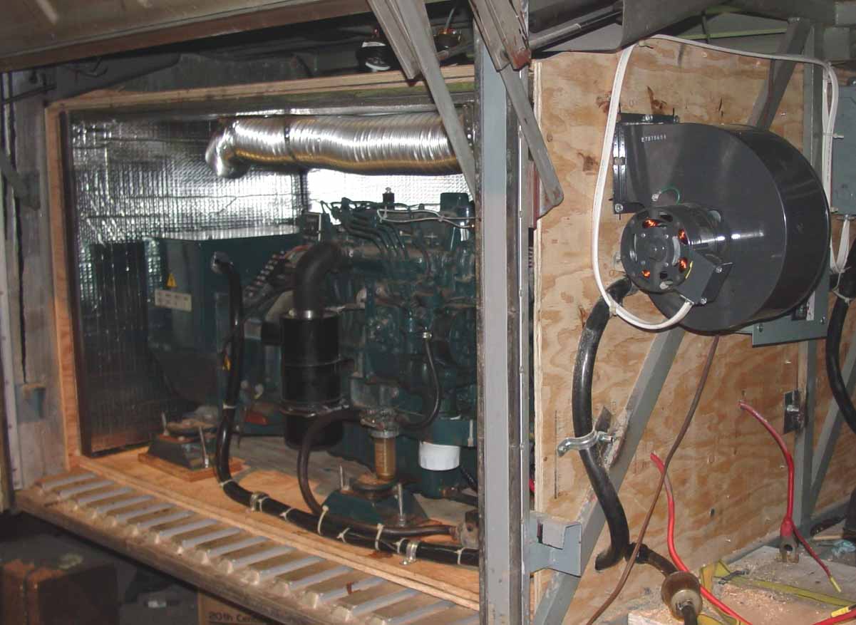
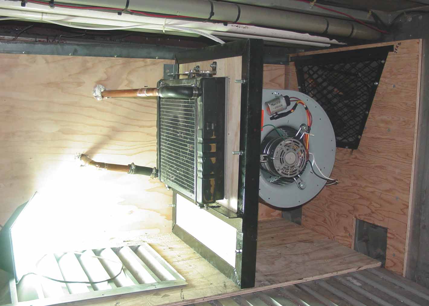
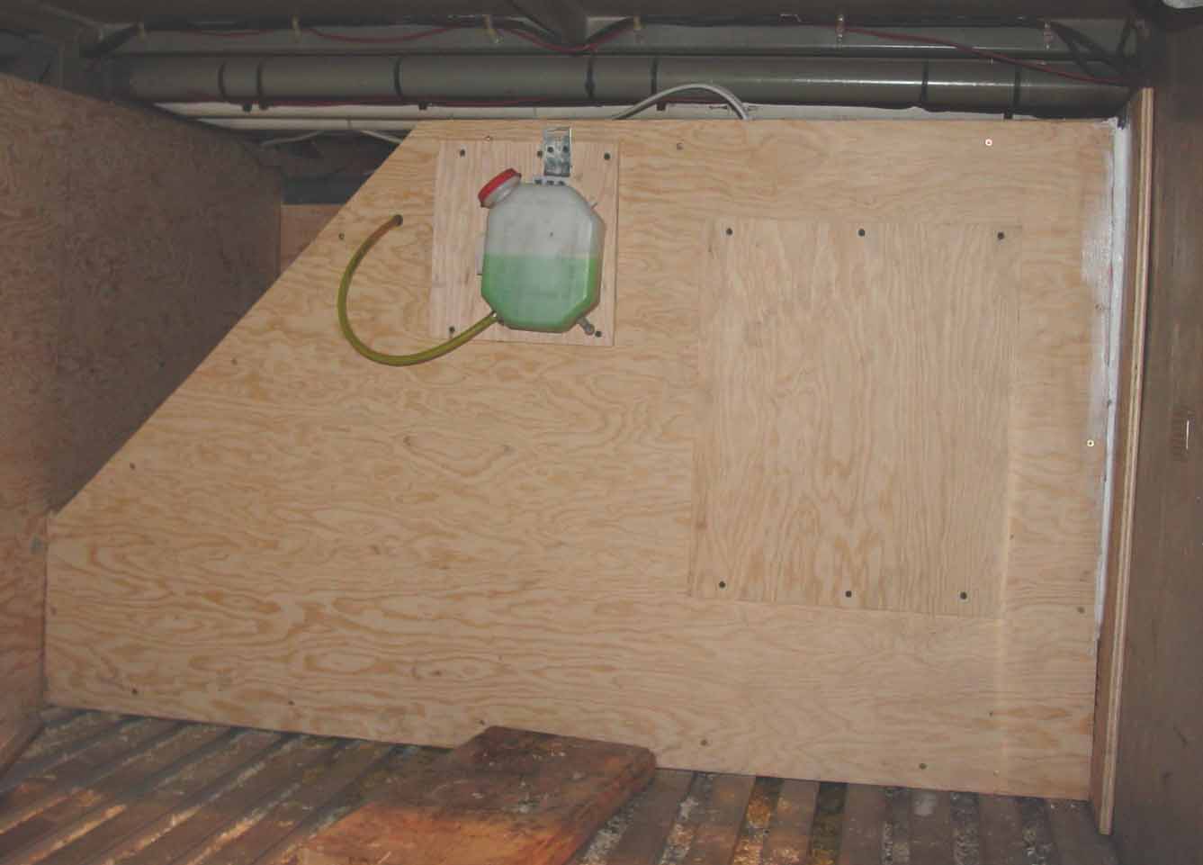
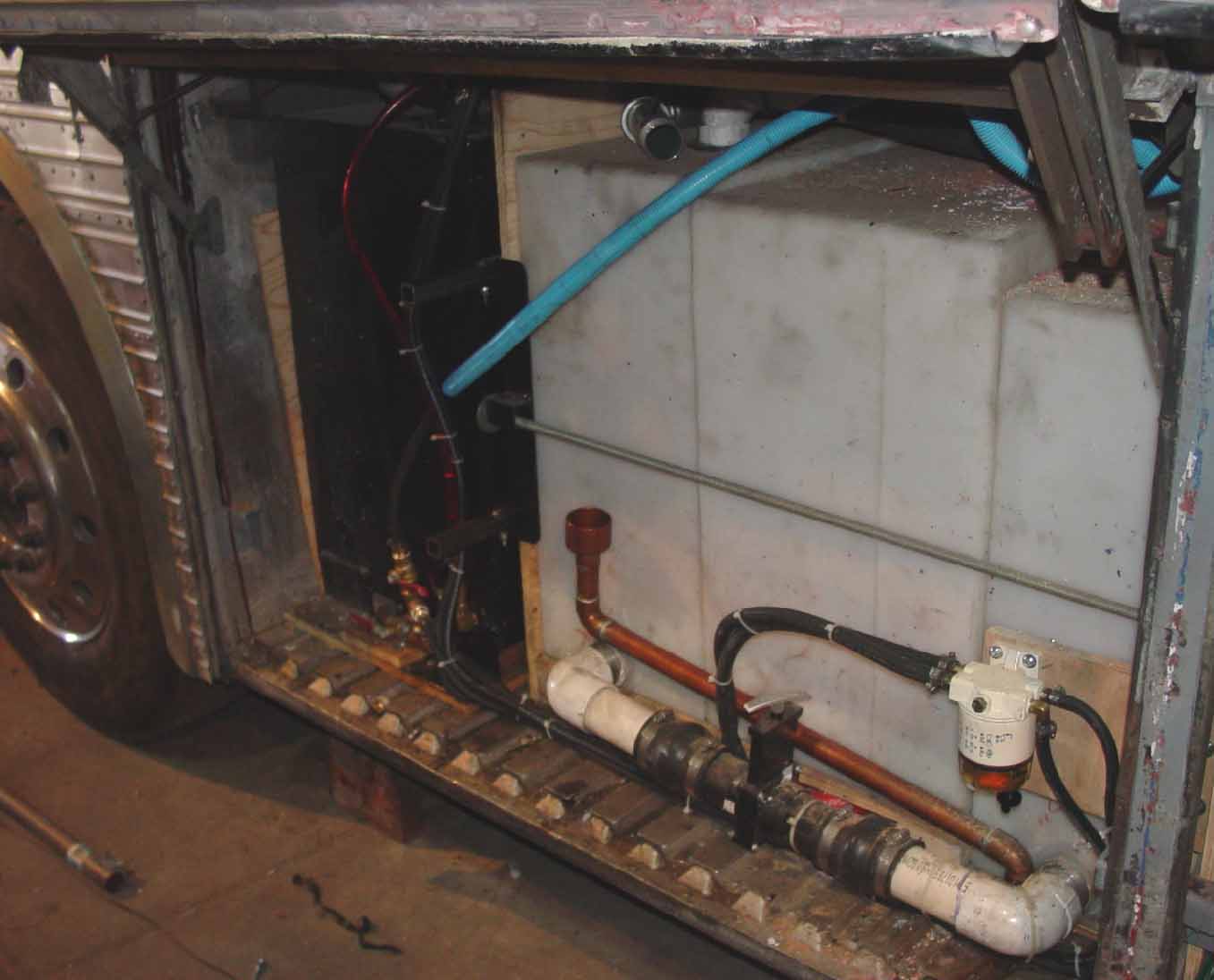
Earlier on this project site, you can see the preparation work for the generator housing and remote generator inlet (in the front bulkhead). In the pictures above, you can see the generator sitting in the fabricated compartment without the front cover. The housing has two layers of plywood separated by 1/8 inch lead sheet. Inside the housing is covered with noise reduction material from Wrico. The unit has rather low noise output. The small squirrel cage fan in the right side of the left photo delivers air to the generator and also cools down the compartment through outlets in the floor. The remote radiator has a large squirrel cage fan that runs whenever the generator is operating. It is large enough that it draws about 10 amps at 120 volts, and really moves the air. The air is drawn in through the bulk head opening (shone earlier) and dumps out the bottom of the bay through a louvered opening that directs the air to the rear. The radiator housing is designed such that air cannot bypass the radiator. It seems to do an excellent job of keeping the water temperature down.
One of the major changes to the exterior was removing the white paint from the beautiful aluminum shiplap siding. In my mind this siding is what give the Eagle its classic look. For some reason the Houston Metro fleet ordered their Eagles with the aluminum painted. I used aircraft paint stripper and a high pressure washer. It took several coats, but the end result is pretty darn good as witnessed by the photo on the left.
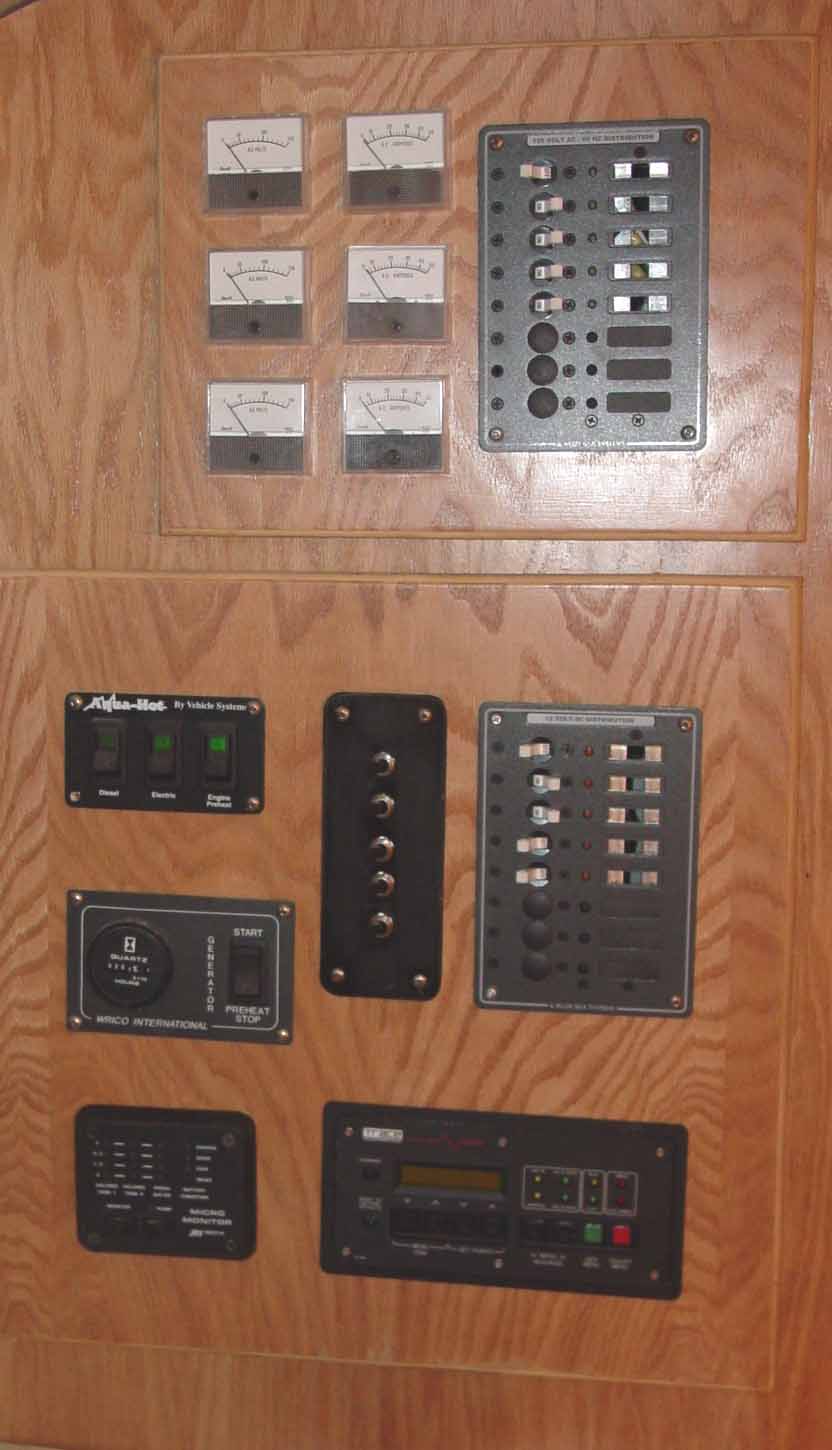
The bay wiring has really grown complex. In the photo at the left, the main breaker panel is in the center of the photo. The transfer switch is in the upper right and the main breaker for the 50 amp service cord is in the lower right. The junction box to the left of the breaker is wired between the input power from the transfer switch and the input to the breaker box. It is used to hook ammeters for each leg of the service in series with the lines. The ammeters measure the load on each leg of the 240 volt service to permit monitoring the balance of the system when the generator is supplying the power. The breaker box to the left of the junction box is the "main" breaker for service from the inverter to breaker panel for the inverter fed circuits (located in the interior of the bus). As you can see, I really fell in love with "smurf" tubing for protection of the wire cables (I also used it to protect some fuel lines as well). I used stranded "marine" wire (Coast Guard approved) for both the 120 and 12 volt circuits. I still have to secure all of the smurf tubing. In the middle photo, the low and high voltage panels are shown. Each service has it's own box in order to keep the low and high voltage wiring separate. The box behind the low voltage panel is a commercial unit while the box for the high voltage panel is custom made in order to fit in the space available (right photo). The high voltage (120 volt) panel is for all of the circuits supplied by the inverter. Both the low and high voltage system use marine type breakers. The gages on the high voltage panel (upper) are three sets of ammeters and volt meters. Two of the sets of gages measure the total system loads, while the third set measures the current and voltage of the inverter loads. The low voltage (12 volt) panel contains the controls for various systems such as generator start/run/hour meter, inverter controller, tank monitors, Aqua Hot, and interior lights (mostly 12 volt).
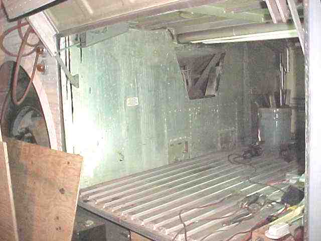
The engine compartment was lined with ultra-high temperature resistant material. The bottom of the bed support was lined with the same material and covered with sheet steel. In addition, a significant part of the exhaust system (including the exhaust manifolds were wrapped with a "wet blanket" form of the same material. The insulation material was then covered with a special high temperature foil material to protect it. This insulation process was done for two reasons. First of all, it would greatly retard penetration of fire into the bus if an engine fire was encountered. Secondly, it greatly reduces the heat radiated into the bedroom of the bus.
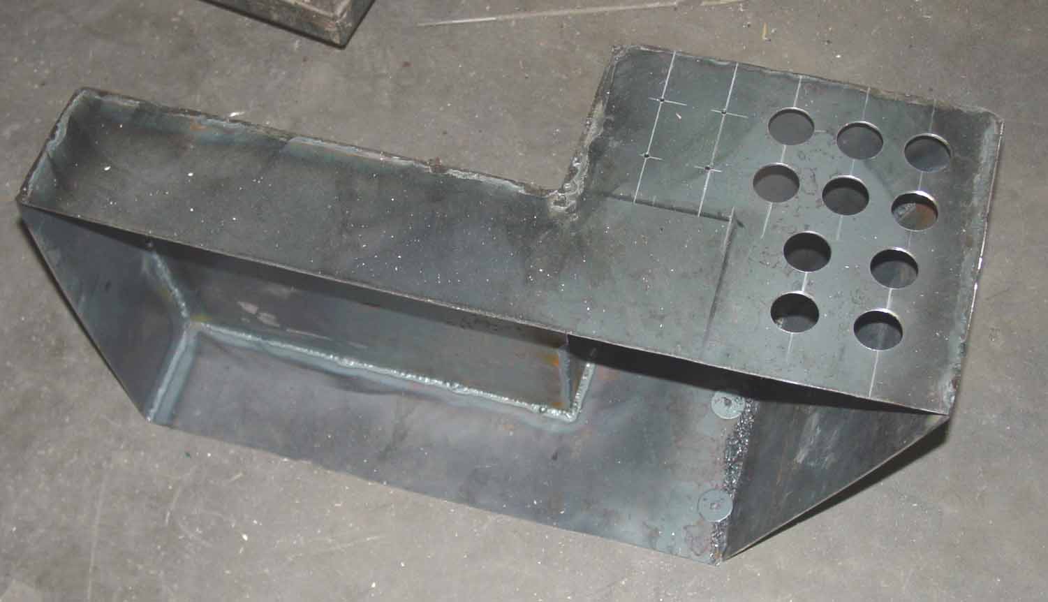
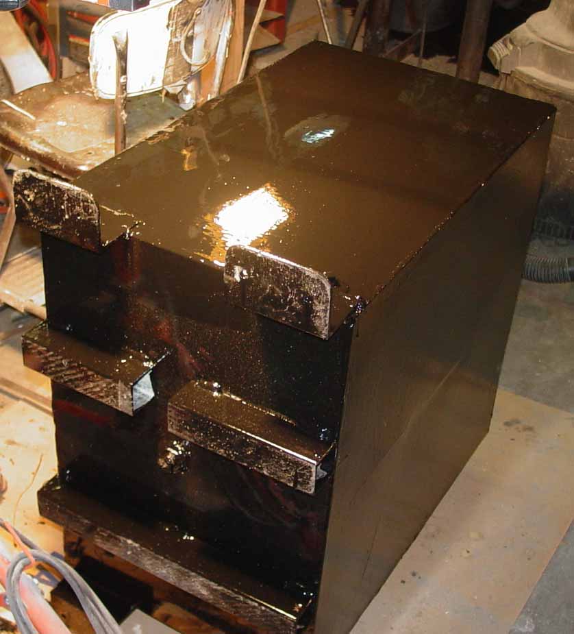
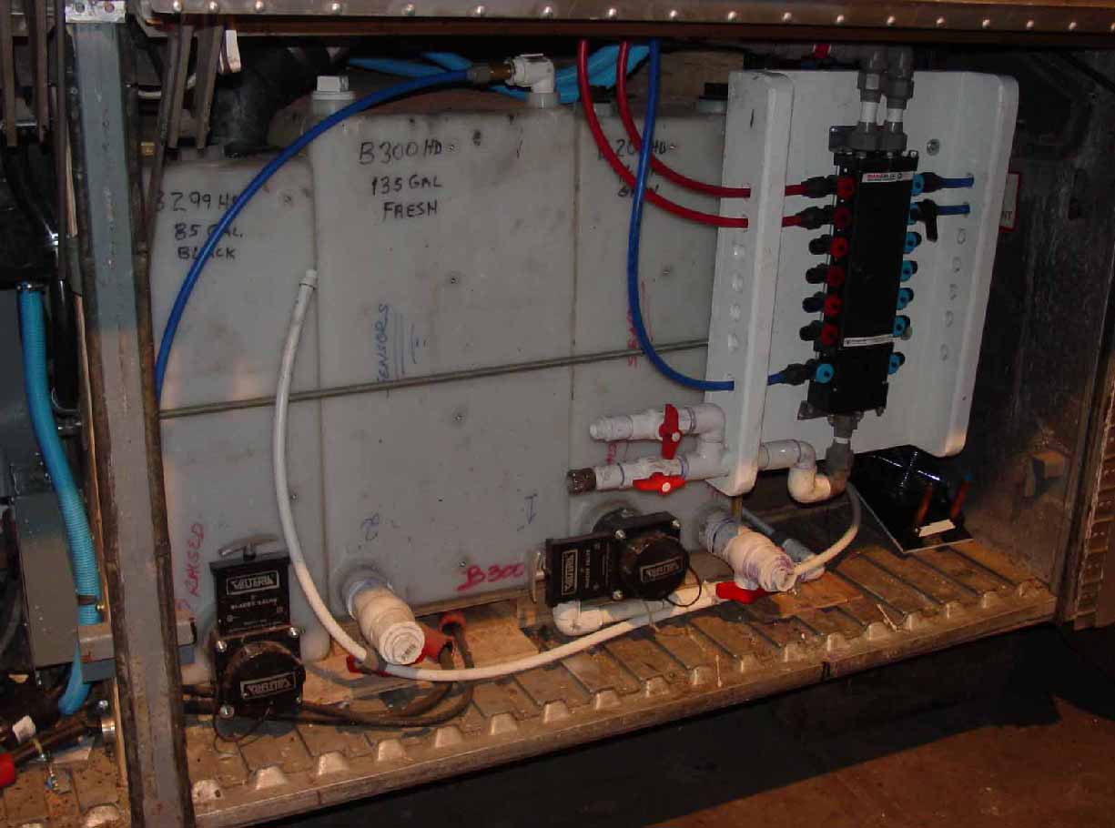
I decided to have a separate fuel tank for the generator and Aqua-Hot heating system. This would assure that I would not run the main (engine) tank low on fuel and would also allow me to better monitor fuel usage for the various components. The tank is made of 1/8 inch steel plate. It is TIG welded on the outside and MIG welded on the inside to assure good filleting on the inside for strength. It also has baffles weld in to minimize fuel slosh. It holds 40 gallons of diesel fuel. The fuel tank is shown mounted in the rear bay behind the water tanks. For
the water/gray/black water tanks, I bought rotomolded polyethylene tanks. I got
them from:
http://www.ardemco.com. I recently went to their website, and was
disappointed. I thought they would list the hundreds of sizes available, but
they don't seem to have that information. They advertise in BC magazine and I
would recommend you support them if they have what you want.
The passenger side view (middle photo) of the water/gray/black tanks shows the dump connection of the gray and black tanks. This connection is designed such that the gray water floods the black tank after it has been drained. This helps clean out the black tank. The driver side view of the tanks shows the drains for both the gray and black tank. In practice the gray tank drain will not be used, because of the process described in the previous paragraph. The photo in the right also shows the Manabloc plumbing manifold. This system puts each water outlet (both hot and cold) on it's own valve and line.
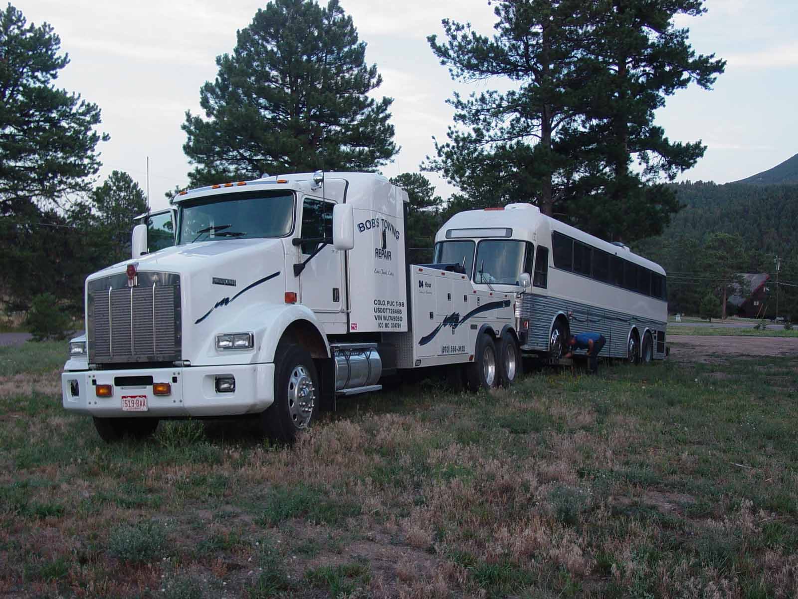
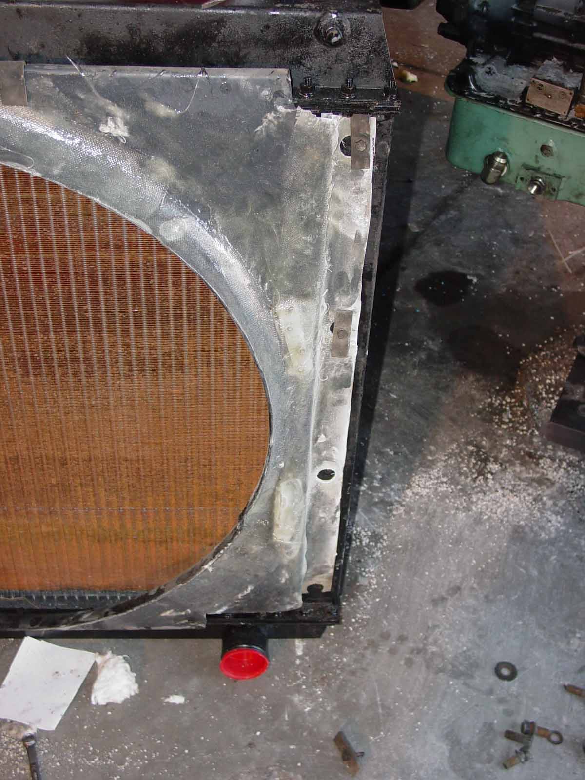
In July and August of 2003, I really put in a lot of time on the bus getting it ready for our annual trip to Bonneville Speed Week. Part of the effort involved a trip to Denver to have the State Patrol inspect the bus to confirm that it qualified to be re-titled as a motorhome. A second trip to Denver was required to get the emission test done (full dynamometer test with a requirement for 20% opacity). During that trip I also had new aluminum wheels and tires installed on the front. Everything was going well until just before I got home. The Voith transmission electronic control system failed. This was at least the third time I had problems with the electronic system. The Voith is a strong transmission, but it is no longer made and the electronics are very complex and almost impossible to trouble shoot. I had been worried about the transmission and had planned to change it some day. Well that day came sooner than later. That very large tow truck had no problem towing the bus, but it was sure embarrassing since all of the neighbors were outside when I came home behind the hook. The middle photo shows the engine transmission cart that I built to remove the drive train. I ordered an Allison HT740 transmission. It was the typical transmission used in these busses. It has a manual control an is almost bullet proof. I chose not to rebuild it, as the supplier assured me that it is a good working unit - I sure hope so, since pulling the engine/transmission is no fun. While I had the engine out, I thought I would have the radiator rodded. Well, that was wishful thinking. The fins were loose on the tubes and the technology was a bit outdated. I now have a new radiator and a receipt for over $2,000! I had had some cooling problems pulling the hills around the house, so that should go away. When I pulled the very large radiator (over 200 pounds I would guess), I found that the shroud was in pretty bad shape. I fiberglassed the shroud to repair and reinforce it. I also replace the belts that drive the fan.
Page 2
|
||||||||||||||||||||||||||||||||||||||||||||||||||||||||||||||||||||||||||||||||||||||||||||||||||||||||||||||||||||||||||||||