|
Our 1985 Eagle 10 Bus Conversion Project Page 4
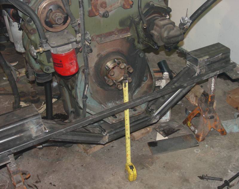
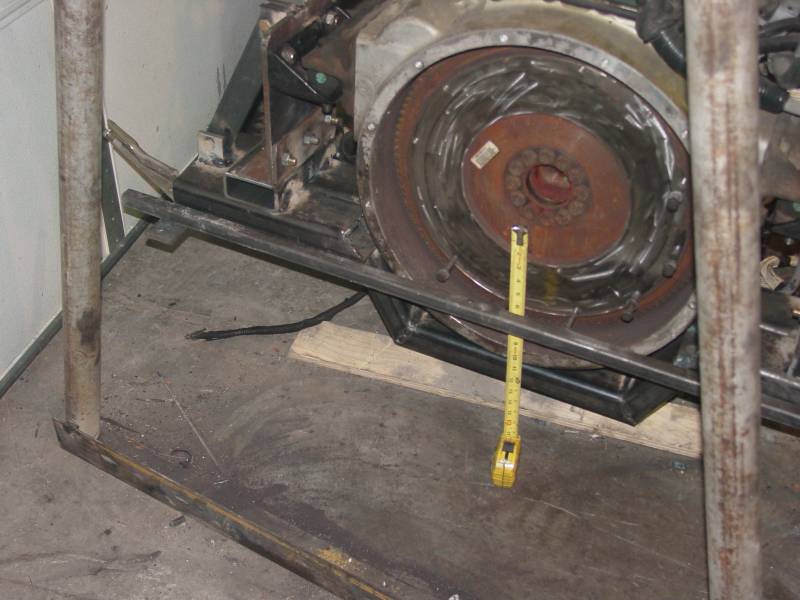
I would like to update the engine mount status. The above discussion is all well and good, but I could not find the correct engine front mount for the IHC application. Also, the Peterbuilt rear mounts were very close to the Freightliner design, but the hole layout was a bit different. Bottom line, I chose to go with new Freightliner mounts - the same as those that came with the engine. This made the fabrication easier. We will see how much vibration this system transmits to the bus structure. Some folks who are installing the Series 60 engine in a bus, design a "unit" mounting system that allows the engine/transmission to be installed using a fork lift. I chose to use a system similar in concept to the 6V92 system and use a dolly to support the engine and transmission for removal and installation. I also chose to make the rear mount uprights replaceable in case I choose to do some modification at a later date. The front mount was fabricated so that the IHC system can be installed at a later date if vibration becomes an issue. The following section details the jack system I fabricated and installed. I updated this section 2/19/12. The update includes the most recent hardware components as well as photos of the front jack system.
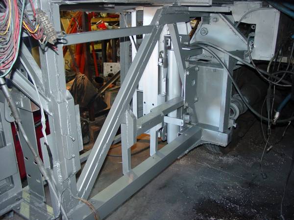
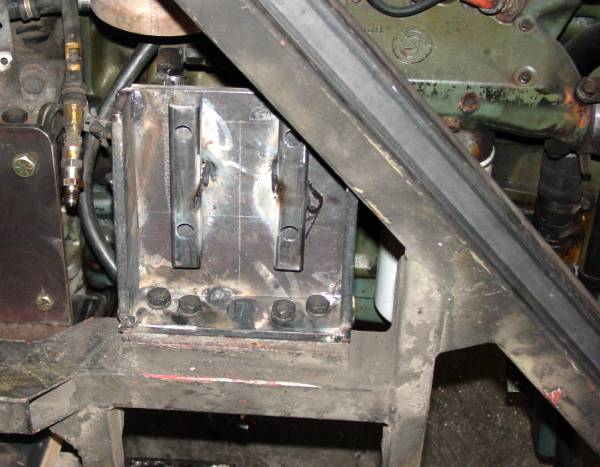
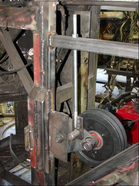
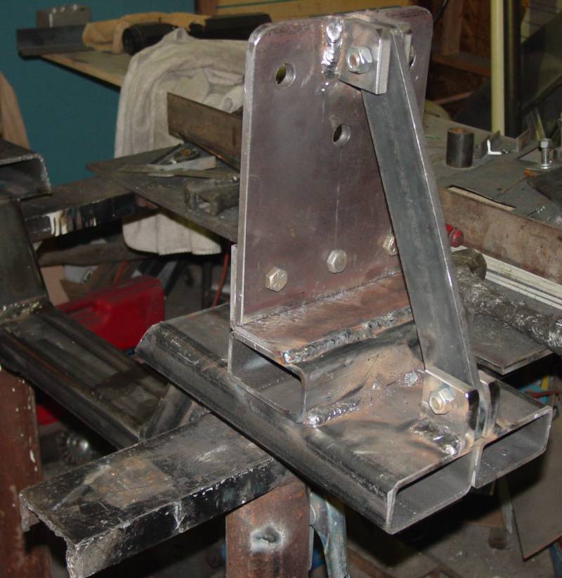
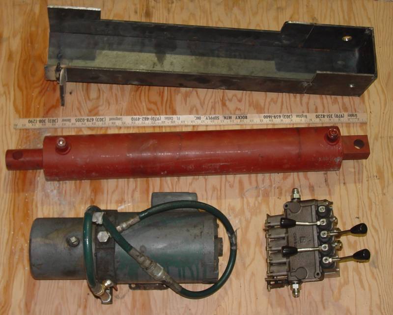
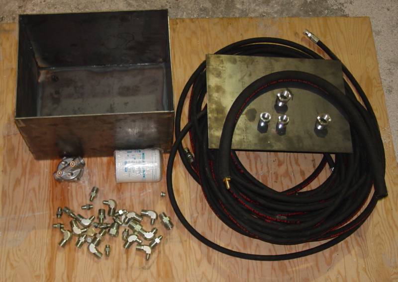
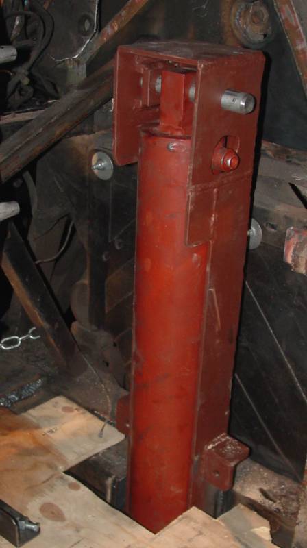
I decided to spend time fabricating and installing the rear leveling jack system, as the jacks would be needed to lift the engine/transmission off of the dolly. The cylinders are Northern Tool (northerntool.com) part number 902424. They have a 4 inch bore, 2 inch shaft, and 24 inch stroke. The first valve I used was a Salami 5 spool 7 GPM item which was purchased from Surplus Center (surpluscenter.com). I chose this valve (part number 9-5356) because it was designed for use with cylinders and had check valves to hold the cylinders in place. The pump is a 110 volt unit that I had from a prior project. The hydraulic supply tank is holds 10 gallons of fluid. My calculations suggest that full extension of all four cylinders would require a bit less than 6 gallons. All of the hoses were custom made. Note: the data above was for the first system I cobbled up. I ended up changing the valve, as the original valve only had two circuits that worked for hydraulic cylinders. Shown in the table below is the current valve assembly I use. I chose to go with a central pump and mechanical valve for my application. Aftermarket system tend to used a combination of pump and cylinder for each position. The central system makes it pretty simple, but requires a bunch of hose. My fabricated cylinder mount is a bit complicated. A person could use 5 inch channel, but I think the beam strength would be marginal. I built heavily reinforced 2 inch wide pads into the mounts. There are two pads. A five inch long pad on the back of the mount and a 3 inch long pad on one side of the mount. The bus structure sits on these pads and the mount is welded to the structure. For the bending moment or pivoting resistance, I am welding a bar to the bulkhead plates shown previously. That will make the mount very sturdy. The rear cylinders are installed behind the rear wheels and are mounted so that the stance is fairly wide. I installed the front jacks in May 2010. About a month prior to that, I installed a hydraulic fan on the charge air cooler. Part of that installation included a two stage engine mounted pump. One stage provides the supply for the power steering and the second stage provides the supply for the fan motor. I plumbed the circuits with a hydraulic quick change coupling in the supply line so that I can disconnect the fan drive and connect the jack system. That works pretty well, as I don't use the jacks all that often - mostly in the shop to service the underside of the bus. The photos of the jack and pump are shown below. I built a hydraulic supply tank out of an old air tank. I welded a plate/flange on the top. A second plate with welded pipe fittings bolts to the flange. That plate has fittings for two different return lines (fan and jack circuits) and a vent. The supply port was a standard port in what is now the bottom of the tank.
Shown below are the components of our bus jack system. Included in the table are pump options. I have tested versions of each of these pumps in anticipation that I would use one of them in the bus. After I obtained the hydraulic fan drive components, it was an easy decision to use the two stage pump to provide the supply for the jack system.
Now back to the engine conversion project.
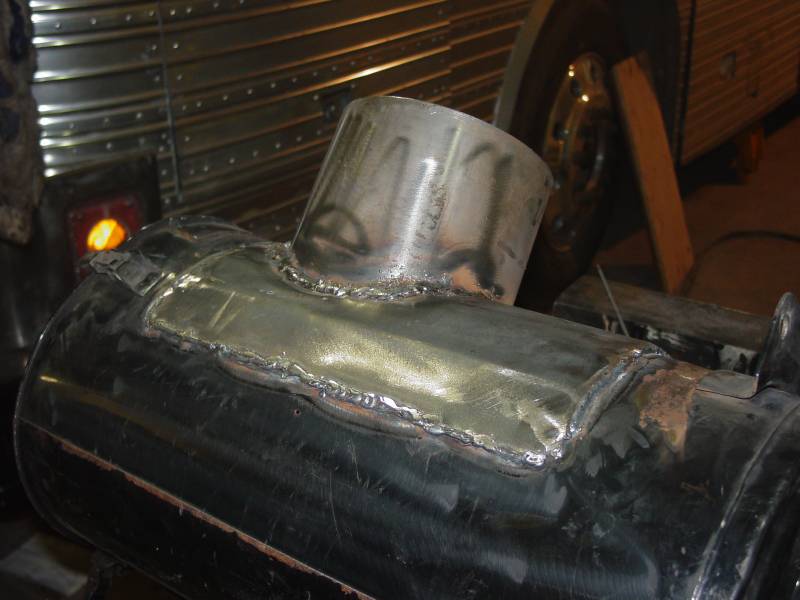
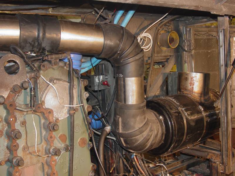
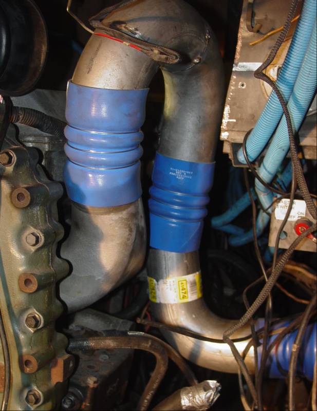
One of the "fun" jobs of an engine conversion is the plumbing for all of the "fluids". The air filter is from the Freightliner that I obtained the engine from. It had cowl induction, so I had to modify it to use 7 inch tubing. The plumbing to the turbo intake uses 5 inch tubing and is relatively straight forward and is made easier by the use of rubber elbows an "hump" hose. The air to air plumbing was a bit of a challenge. As I had noted earlier in this project report, I mounted the charge air cooler in the compartment that used to house the air conditioning condenser. The plumbing from the turbo to the charge air cooler will be pretty straight forward, but the plumbing from the cooler to the intake is a bit convoluted as shown in the above photo. I have started on the cooling plumbing. The major complication there is that the 6V92 used 2.75 inch OD tubing while the Series 60 uses 2.5 inch tubing. I am using some exhaust tubing bends and reducers to get the coolant to where it needs to go.
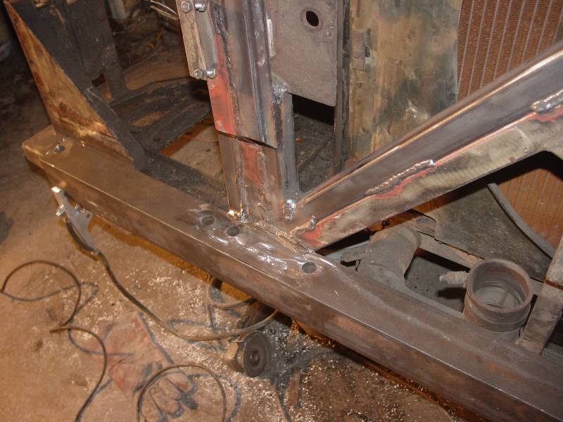
All of the engine cradle system was reinforced in various ways. The down tubes were all double tubed with thick wall 1.5 inch square tubing. The engine rails had 3 X 3.5 X .25 angle iron added to the existing rails. The rear cross member (at floor level) was heavily reinforced, since part of the existing member has to be removed (documented earlier in this project report). All of this reinforcing was done to offset any loss of strength due to corrosion or fatigue, plus the fact that the engine is heavier and front engine mount is further back on the frame. In addition, I wanted to be able to pull a reasonable size trailer at some later point in time and the hitch relies on the engine cradle structure integrity. After all of the welding was done, I painted everything with Rust Bullet protective paint (http://www.rustbullet.com/)
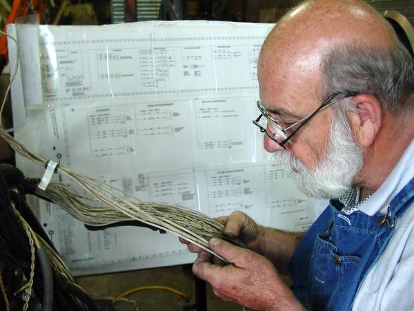
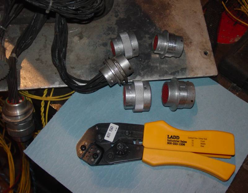
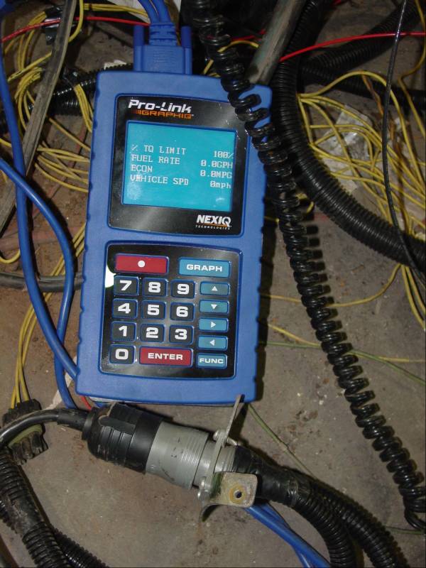
Both the Series 60 and the Eaton AutoShift transmission control harnesses are terminated with Deutsch connectors. I have purchase mating connectors so that the control harnesses will be connected at both ends via Deutsch connectors. The wiring harness for the engine will contain 21 wires while the transmission harness will 6 single connectors plus two sets of shielded twisted pair cables (12 wires total). It would be impossible to fabricate the looms without good wiring diagrams (as show in the photo in the upper left). It also helps to use "cheaters" to read the labeling on the OEM wires (grin). Each of the looms was made with 14 gauge wire (larger than called for). The looms were made to length and then tested for correct connection in each Deutsch connector. Even though I was very careful, I found a few incorrect wire terminations (kind of confusing since the two ends are mirror images). The two looms had extra wires added for any future needs, or for repair if needed (see photo on the right). The looms were then run in the PVC conduit I had installed in the "spine" of the bus. Two of the photos above show the "bench" testing that was done before the engine/transmission was installed. Each engine and transmission function that could be tested without the engine running was checked using a Pro-Link scanner. This scanner was also used to set several engine variables. The AutoShift transmission need to communicate with the engine via a J1939 data link. This link both relays data and controls various engine/transmission functions. As I said earlier, the engine and transmission were purchased separately. This gave me the additional challenge to get them "talking" to each other. The engine was a DDEC III and the manual would suggest that the ECM can have the J1939 data link can be activated (the external connections are present). However, activating that link must be done by Detroit Diesel. I watched the dealer get the DD main computer permission to activate, but several tries proved fruitless. After several calls to the factory it was agreed that I would have to upgrade to a DDEC IV ECM. That is an expensive proposition, but I did not have a choice. The conversion is drop-in. I am told that this ECM is more robust and the software can be upgraded if needed (the DDEC III is no longer supported). Editor's note: I have added the wiring harness connection data for my engine and AutoShift transmission on page 6 of this document).
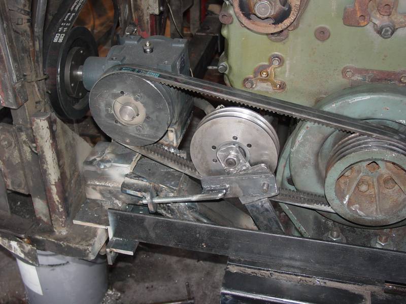
On the Eagle bus, the radiator and cooling fan are on
the driver side of the bus and are at a right angle to engine. On some
buses the fan is driven by a hydraulic system. I chose to use a
belt/gear box drive system. The gear box is a Hub City model 600 (part
number 0220-03409). I then used industrial sheaves (as opposed to
automotive sheaves which can not be purchased) for all of the sheaves other
than the fan clutch and crankshaft sheaves. This fan and crank sheaves
have automotive belt profiles and the industrial sheaves have entirely
different grooves. However, with care, sheaves and belts can be chosen
which will run in the automotive fan and crank grooves (I designed belt
drives for 34 years while employed at the Gates Rubber Company).
The belts on the crank to gearbox drive are 2 ea.
5VX630 and the gear box to fan clutch are 2 ea CX90. The sheaves and
idler sizes were chosen so that the idler and sheave could be interchanged
to change the ratio in each drive.
The idlers were made with special Gates idler bushings
(shown in the middle photo). I was involved with the design of these
idlers which were specially designed for one of our premier product lines.
They are very robust and make mounting an idler a "snap).
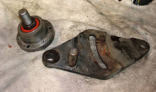
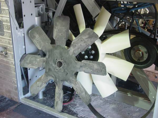
I chose to retain the fan clutch concept from the DDEC
engine since it is a part of the control system in the ECM. However,
the fan clutch that came with the engine was shot. After looking at
all the belt/sheave conbinations, I chose a Cummins fan clutch from an N14
engine since it had the groove profile that were reasonably compatible with
"C" section industrial sheaves. That clutch and the idler with the
idler bushing are shown in the 4th photo from the left. I also
installed a draw bolt on the gear box to clutch fan drive idler to make it
easier to tension the drive. The idler bracket is the stock Eagle
unit. However, it is very hard to apply tension to the belt and the
draw bolt solves that problem. In the photo, the bolt is terminated on
a cross member above the idler. That proved to be a design problem and
it is now terminated on the vertical member behind the idler so that the
bolt tilts back about 45 degrees.
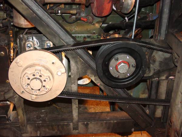
The crank to gear box drive is shown in the left
photo. The draw bolt is designed so that a spring can be placed behind
the terminating bracket if needed. The engine rocks slightly about the
engine mounts and that sometimes causes belt problems with systems that are
not "compliant". For now I will run the drive without the spring and
see if any issues develop. The photo on the right shows the new
bracket that adapts the fan clutch hub to the original Eagle fan hub
bracket. The center photo shows the new high performance fan that was
chosen for the drive. A new fan was required, as the gear box changed
the direction of rotation from the original drive, plus the fact that the
original fan was very heavy and would have caused problems with the fan
clutch. The new fan was defined from the following website:
http://kit-masters.com/
Page 4
|
||||||||||||||||||||||||||||||||||||||||||||||||||||||||||||||||||||||||||||||||||||||||||||||||||||||||||||||||||||||||||||||||||||||||||||||||||||||||||||||||
.JPG)
.jpg)
.JPG)